
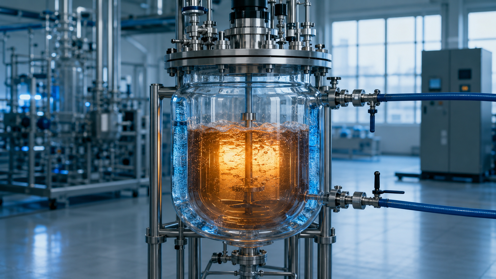
When an exothermic reaction moves from flask to pilot scale, heat removal becomes the limiting factor — and it must be engineered into the jacket geometry and a dedicated emergency cooling circuit before the first larger batch is run.
TL;DR / Key Takeaways
- Exothermic reactions do not scale linearly: reaction heat grows with volume while the surface available to remove it grows more slowly, so heat removal — not heat addition — governs safe scale-up.
- Jacket geometry (full jacket, half-pipe coil, single vs. dimpled wall) sets the available heat-transfer area, the coolant flow regime, and the reactor’s real cooling capacity. It is a safety decision, not only a performance one.
- An emergency cooling circuit is a second, independent line of defence sized against the worst credible case — not the normal duty. It must engage without compromising routine temperature control.
- Specify thermal safety from boundary conditions and measured reaction data, then document it. This is where a custom glass reactor design earns its place over a purely catalogue configuration.
Introduction
A reaction that behaves impeccably in a 1-litre round-bottom flask can become the most dangerous step in a process when it is run at 30 or 100 litres. The chemistry has not changed. What has changed is the reactor’s ability to take heat away fast enough. For German process engineers, the question is rarely whether a reaction works once, but whether it can be repeated under controlled conditions — and for an exothermic step, “controlled” means the cooling system can always win the race against the reaction.
That race is the essence of a thermal runaway: reaction rate rises with temperature, and if the heat generated outpaces the heat removed, temperature and rate feed each other until the batch boils, vents, or decomposes. Preventing it is not a matter of operator vigilance alone. It is designed in — into the geometry of the jacketed glass reactor and into a dedicated emergency cooling circuit — long before the scale-up from bench to pilot begins. This article sets out how both should be specified.
Why Heat Removal Governs Exothermic Scale-Up
Start with the boundary conditions. A reaction generates heat in proportion to the mass of reactants, which scales with volume. The reactor removes that heat across its jacketed surface. These two quantities do not scale together.
For a geometrically similar vessel, volume grows with the cube of the linear dimension while heat-transfer area grows only with the square. Double every dimension and volume rises eightfold, but the wall area available to cool it rises only fourfold — so the specific cooling area, the square meters of jacket per liter of contents, is roughly halved. Scale up again and it halves again. This is why a reaction that a flask shrugs off can overwhelm a pilot vessel: the heat is still there, but proportionally far less wall through which to remove it.
Three levers set the actual heat-removal rate: the overall heat-transfer coefficient (U), the effective area (A), and the temperature difference between contents and coolant (ΔT). Borosilicate glass has a lower thermal conductivity than stainless steel, so a glass reactor typically works with a modest U and compensates through area and ΔT. That trade-off is exactly why jacket geometry and coolant strategy deserve deliberate specification rather than a default choice. Good temperature control at bench scale is the baseline; preserving it at volume is the engineering problem.
Specifying Jacket Geometry for Thermal Safety
The jacket is the reactor’s primary thermal interface, and its geometry decides how much of the theoretical cooling capacity is actually usable. When specifying a jacketed glass reactor for an exothermic process, several decisions matter.
Full jacket vs. half-pipe / coil paths. A conventional full jacket surrounds the vessel with an annular coolant space. It is simple and gives large contact area, but at scale the coolant can channel or stagnate, leaving zones of poor exchange. A guided or half-pipe-style flow path forces the coolant along a defined route at higher velocity, which sustains turbulence and a more uniform wall temperature. Higher coolant velocity generally raises the film coefficient and therefore U — the cooling you specified is the cooling you get.
Turbulent, not laminar, on the service side. Much of the resistance to heat transfer often sits in the coolant film, not the glass. A jacket designed so the coolant stays turbulent across the full operating flow range removes heat far more predictably than one where flow drops into the laminar regime at reduced duty.
Uniformity and thermal lag. Localized hot spots near the addition point or a poorly swept baffle region are where a runaway typically nucleates. Jacket geometry, internal mixing, and dosing location have to be considered together, because uneven wall temperature and thermal lag both delay the reactor’s response exactly when speed matters most.
Area as a safety margin. Because specific cooling area falls as volume rises, the jacket should be sized against the reaction’s peak heat-release rate with margin, not against its average. At HWS, our engineers usually start from that peak duty and the coolant available on site, then design the geometry to deliver it — which is often where a custom configuration replaces a standard one.
Emergency Cooling Circuits: The Second Line of Defense
Normal jacket cooling is designed for the process as intended. An emergency cooling circuit is designed for the process as it might fail: a dosing pump that does not stop, a mixer that stalls and then restarts onto an accumulated reactant charge, a coolant supply that warms. It is a separate safety function, and it should be specified separately.
Independence. The emergency circuit should not share its single point of failure with normal control. That can mean a dedicated chilled-fluid or brine supply, a separate valve and line that fails to the safe (open, flowing) position, and actuation that does not depend on the same controller running the batch. If losing one pump disables both normal and emergency cooling, there is no second line.
Size it to the worst credible case, not the duty. The relevant questions come from the reaction’s thermal data: the adiabatic temperature rise if cooling is lost, the maximum temperature of the synthesis reaction (MTSR), and how quickly the system would reach a hazardous rate. The emergency circuit — coolant temperature, flow, and added area such as an internal coil — must be able to absorb that worst-case heat load and hold the batch below the temperature where decomposition or pressure generation begins.
Response time. Capacity that arrives too late is not protection. Valve actuation, coolant transport lag, and the reactor’s own thermal inertia all consume time the reaction does not give back, so the design target is the time-to-maximum-rate under adiabatic conditions, with margin.
Do not compromise routine control. A common mistake is bolting on emergency capacity in a way that degrades everyday temperature stability — an oversized coil that makes fine control sluggish, or a shared loop that introduces disturbances. The two functions coexist best when designed together from the start.
A Practical Specification Workflow
A German engineering approach starts with the boundary conditions and works outward. In practice, for an exothermic scale-up:
- Characterise the chemistry. Obtain the heat of reaction, peak heat-release rate, adiabatic temperature rise, MTSR, and onset of decomposition — ideally from calorimetry, not assumption.
- Set the thermal duty. Convert peak heat release into a required removal rate at the intended scale, and check it against the available coolant temperature and the specific cooling area at that volume.
- Design the jacket to meet peak duty with margin. Choose geometry and coolant flow to deliver U, A, and ΔT for the peak, not the average.
- Add an independent emergency circuit sized to the worst credible loss-of-cooling scenario, with defined actuation and response time.
- Verify uniformity and control interaction — mixing, dosing location, sensor placement, and the interplay of normal and emergency cooling.
- Document the basis of safety. Recording the assumptions, data, and design margins turns thermal safety into something that can be reviewed and repeated, which aligns with the quality-risk-management thinking behind the ICH quality guidelines.
Conclusion
Exothermic scale-up is, at heart, a heat-removal problem disguised as a chemistry problem. Because reaction heat and cooling area scale differently, the reactor that carried a reaction safely at bench scale will not necessarily carry it at pilot scale — unless jacket geometry and an independent emergency cooling circuit have been specified against the reaction’s real thermal data. Treating thermal safety as a design input, not an operational afterthought, is what makes an exothermic process both safe and reproducible.
This is precisely where a purely catalogue-based approach can fall short. When peak duty, coolant conditions, geometry, mixing, and an emergency circuit all have to align around one specific reaction, the right answer is usually a reactor designed for it. At HWS, we build custom glass reactor solutions around the process first, so that thermal safety is engineered in rather than added on.
CTA: Discuss a Custom Glass Reactor Solution
Planning an exothermic step for pilot or production scale? Contact HWS engineers to specify jacket geometry and an emergency cooling circuit sized to your reaction’s thermal data — and request a custom glass reactor solution built around your process requirements.